Circuits That Get Chaos in Sync
| JOSEPH NEFF and THOMAS L. CARROLL devised the experiments
described here by adapting Carroll's design of the first electronic circuits
to exhibit synchronized chaos. Neff, who built the circuits during his senior
year at the College of Wooster, recently graduated and is currently pursuing
graduate studies in physics at the Georgia Institute of Technology. He programs
computers to investigate chaos. Carroll , who received his Ph.D. in 1987
from the University of lllinois, works at the U.S. Naval Research Laboratory.
He looks for applications of chaos and has patents pending on some chaotically
synchronized circuit designs. |
Chaos is not always so chaotic. In some sense, it can be
predictable: two systems can be designed so that one exhibits exactly the
same chaotic behavior as the other. In other words, the systems would be
synchronized. Such devices might be useful for encrypted communications.
For example, one of the systems could conceal a message within the chaotic
signal. Only someone who possesses the second system would be able to decode
the transmission, by subtracting the chaotic signal and leaving behind the
message [see "Mastering Chaos," by William L.
Ditto and Louis M. Pecora, page 62].
Louis M. Pecora of the U.S. Naval Research Laboratory first
came up with the idea of synchronized chaotic systems. He and one of us (Carroll)
used a computer simulation to show that such a phenomenon can exist. The
next step was to demonstrate the idea using physical systems-specifically,
electrical circuits, which are accessible and inexpensive. The first circuit
that Carroll built to display synchronized chaos was based on a design devised
by Robert Newcomb of the University of Maryland.
Although the circuits described here are simplified versions
of Newcomb's, experience with circuit assembly might be helpful. A good
introduction to chaos in electrical circuits, using only a diode, an inductor
and a resistor, appeared in this column last year [see "How to Generate Chaos
at Home," conducted by Douglas Smith; Scientific American, January 1992].
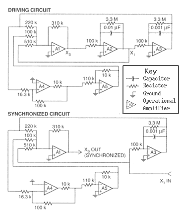
Basically, the setup will consist of two circuits: a driving
circuit and a synchronized circuit [see illustration below]. The two are
identical except for an important component missing in the synchronized circuit.
The two circuits are connected at a single point. The chaotic output of the
synchronized circuit will match that generated by the driving circuit if
both circuits are correctly built.
 |
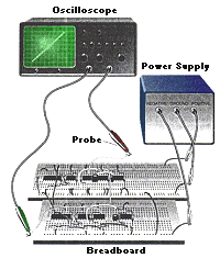 |
Chaotic Circuits produce the same output. They draw current
from a 12- volt power supply and are probed by an oscilloscope (left). The
values for the components used should match those shown in the
schematics (above) to within 1 percent.
|
Before buying the electronics parts and constructing the two
circuits, make sure you have an oscilloscope, breadboards and a power supply
that can deliver 12 to 15 volts of direct current. ( Breadboards are thin
sheets of plastic that have holes to accommodate electronic components; purchase
ones that will hold the positive, negative and ground terminals from the
power supply.) The power supply and breadboards are cheap and easy to come
by.Oscilloscopes, unfortunately, are expensive; they start at about $500.
You can sometimes buy a cheap, used oscilloscope at a "hamfest" -a flea market
for ham radio enthusiasts. If you do not wish to purchase an oscilloscope,
you might be able to get access to one at a local college laboratory.The
device should provide two channels and be able to plot the input to the channels
against each other.
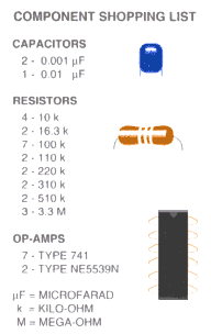
For the circuits themselves, you will need various resistors,
capacitors and integrated chips called operational amplifiers (op-amps).
A list of such items and the minimum quantity you need appears below. We
recommend buying more than the minimum, because it is easy to make connection
errors that can burn out the components, especially the op-amps.
Because the two circuits must be as similar as possible, it
is essential to use resistors and capacitors that have high tolerances. Look
for resistors rated to be accurate within 1 percent and capacitors made from
polypropylene, which do not leak much current. All but two of the op-amps
are generic type 741. The exceptions, labeled "A4" on the schematic [see
top illustration on preceding page], are so-called high-frequency uncompensated
op-amps. The particular ones used here were type NE5539N. These two are the
most critical components of the circuits, as they are ultimately responsible
for keeping the circuits synchronized.
The components we used were purchased from Digi-Key Corporation
in Thief River Falls, Minn. The total price was less than $30. When ordering,
remember to ask for the pin diagrams for the op-amps, which contain several
connections that all look alike. The specification sheet describes the
configuration of the pins so that you will know which ones to use.
To decrease the possibility of wiring error, it is best to
lay out the circuits according to the schematics before connecting them.
Start with the op-amps, using one breadboard for each circuit. Observe that
the synchronizing circuit is identical to the driving circuit, minus an op-amp
and its ancillary components.
The next step is to make the power connections (be sure the
power supply is unplugged before beginning). Only the op-amps draw current.
Attach wires from the positive, negative and ground terminals to separate
rows that run along the top and bottom of the breadboard. These rows are
dedicated solely to providing voltage to the electronic components. Use the
op-amp spec sheet to determine the appropriate connections from the pins
to the rows.The ground wires should be as short as possible because long
ground connections can pick up noise, which would keep the circuits from
synchronizing.
After hooking up the power supply, begin connecting the components
systematically. Although the schematics are simple, it is easy to create
a mess. Short, colour-coded wires make the circuit convenient to read and
check over. Take several different visual walks through the circuits to verify
that all of the connections are correct. Writing down the colour codes of
the resistors next to their values on the schematic may speed up this process.
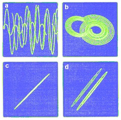 |
OSCILLOSCOPE PATTERNS typically found in working synchronized
circuits are shown above. The chaotic output from one circuit is revealed
by a plot of output voltage over time (a); several sweeps are shown. Plotting
the output from A2 against that from A3 yields a chaotic attractor (b). Comparing
the output of both circuits at X5 shows the circuits are perfectly
synchronized (c) or partially so (d). |
Once you are satisfied that your circuits are correct, connect
the synchronizing circuit to the driving circuit at the points marked
"X1" on the schematic. Notice that as a result of the connection,
the two circuits have the same nonlinear driving component (the subsystem
that uses the A2 op-amp). Connect each channel of the oscilloscope to the
points marked "Xs" on the schematic. Each such point is located
just after the A1 op-amp. Make sure that the circuits and the oscilloscope
all have the same ground - that is, the grounding wire attached to the
oscilloscope's probes should be hooked up to the same ground line as the
circuit.
Check the circuits several times before plugging in the power.
If you burn out one of the op-amps, you can plan to spend at least a few
minutes trying to figure out which component is broken and replacing it.
You can verify that the circuits are producing chaos by displaying information
from one channel only. If that circuit's output is chaotic, the oscilloscope
image will not remain stable on any setting. Instead it produces a pattern
similar to a sine wave that rapidly changes in amplitude.
A detailed explanation of why chaos arrives in the driving circuit
is rather complex. Briefly, the two integrating op-amp components (the op-amps
that have capacitors, labeled "A2" and "A3") are connected in a loop to generate
a sine wave. The op-amp components A4 and AS amplify this sine wave, causing
its amplitude to increase exponentially over time. Once the signal reaches
a certain amplitude, the high-frequency op-amp (A1) brings the amplitude
to zero and starts the process all over again. Chaos creeps in during the
switching, when A1 resets the circuit.
You can see if your circuits are producing synchronized chaos
by plotting the output of one circuit at Xs with that of the other.
If the circuits are perfectly synchronized, the oscilloscope will produce
a straight line angled at 45 degrees. Because of the switching, the
synchronization will probably not be exact. Two broadened, parallel lines
may be the result instead.
Do not be disappointed if the circuits fail to synchronize
on the first try. Check for faulty connections. The circuits are rather fussy,
so any poorly made connections could wreck the synchronicity. A faulty op-amp
could be the culprit. You might find that both circuits generate chaos but
are not synchronized. There are two possible explanations. One, components
that are supposed to be nearly the same may differ too much; for example,
two resistors designated as 1,000 ohms may turn out to be 950 and 1,050 ohms.
Two, the response time of the high-frequency op-amps may be insufficient,
in which case the op-amps should be replaced.
Once the synchronizing chaotic circuits are working properly,
you can create the form of
message encryption envisioned
by Pecora and Carroll. You will need two more op-amps and several large
(high-impedance) resistors. With these components, you can easily build two
"summing-amplifier" circuits. Such circuits add two signals together and
then invert them. These two circuits are connected to the driving and
synchronizing circuits [see illustration below]. The message we encoded was
a simple sine wave created by a function generator. The sine wave is fed
to one of the summing-amplifier circuits, which combines the sine wave with
the chaos generated by the driving circuit and inverts the total signal.
Amid the chaos, the sine wave is almost impossible to decipher.
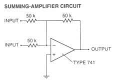 |
Summing Amplifier Circuit
(left) marries an input signal with a chaotic signal and then
inverts the combination. Two such circuits, when connected
to the synchronized chaotic circuits, produce a form of encrypted
communication (bottom).
|
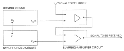 |
The synchronizing circuit, however, can readily extract the
message from the chaos. Because the synchronizing circuit produces the same
chaotic pattern as the driving circuit, all one has to do is add the
synchronizing circuit's chaotic signal to the driving circuit's total (inverted)
signal. What is left is the message. The second summing-amplifier circuit
does this job and reinverts the sine wave to its original form.
The summing-amplifier circuits may cause the entire system to
behave quite erratically. the image on the oscilloscope may blow up. The
problem is that the external devices drain some current and thereby jolt
the circuits from one so-called
chaotic attractor-a pattern around which
the chaotic signals tend to settle-to another.
Large resistors help to alleviate the problem by preventing
current drain. We used resistors of 60 kilo-ohms and one mega-ohm, although
50kilo-ohms will probably do. Another way to get the circuit back to a single
attractor is to short out an op-amp periodically. Briefly touch a grounded
wire to the output of one of the op-amps (preferably the ones with capacitors).
This process randomly resets the state of the circuit. The op-amps will not
be damaged so long as the shorting is brief. Turning the power supply off
and then on again will also work.
To hear the message, you will need to amplify the output. Op-amps
do not deliver much current (and the high-impedance resistors do not help
matters). A stereo system is a nice solution.Alternatively, a basic electronics
handbook will detail how to build simple amplifying circuits to drive a small
speaker.
You might try to encode signals more complex than sine waves. You can send
audible messages by using a microphone, which converts sound waves into
concealable electrical signals. Or you can try sending Morse code: each "click"
sends a constant voltage signal. On the other end, you can wire up a small
light bulb or a light-emitting diode (known as an LED), which should flash
in unison with the clicks if the circuits are working properly.
You can also demonstrate the effects of attractors in chaos
by plotting the output of one of the integrating op-amps versus its neighboring
op-amp. Such an input produces a spectacular pulsating spiral pattern and
is evidence for a single attractor. Feel free to change some of the components
to see what happens. Remember, you are trying to create chaos.
CHAOS ON A CHIP. For the first time physicists have shown
that well structured chaos can be initiated in a photonic integrated circuit.
Furthermore, this represents the first time scientists have been able to
study optical chaos at gigahertz rates. The output of a semiconductor laser
is normally regular. However, if certain laser parameters are tweaked, such
as by modulating the electric current pumping the laser or by feeding back
some of the laser’s light from an external mirror, the overall laser
output will become chaotic; that is, the laser output will be unpredictable.
To make the chaos even more dramatic (and exploitable) Mirvais Yousefi and
his colleagues at the Technische Universiteit Eindhoven (in the Netherlands)
use paired lasers, lasers built very close to each other on a chip in such
a way that each affects the operation of the other. The Eindhoven chip, using
the paired-laser mutual-perturbation approach to triggering chaos, is the
first to exhibit chaos directly-revealing telltale strange attractors on
plots of laser power at one instant versus laser power at a slightly later
instant-rather than indirectly through recording laser spectra. Looking ahead
to the day when opto-photonic chips are covered with thousands or millions
of lasers, the Eindhoven approach could allow troubleshooters to pinpoint
the whereabouts of misbehaving lasers---not only that but possibly even exploit
localized chaotic effects to their advantage. According to Yousefi
(m.yousefi@tue.nl) other possible uses for chip-based chaos will be the business
of encryption, tomography, and possibly even in the establishment of multi-tiered
logic protocols, those based not on just on the binary logic of 1s and 0s
but on the many intensity levels corresponding to the broadband output of
the chaotic laser system. (Yousefi et al., Physical Review Letters, 26 January
2007; text at www.aip.org/physnews/select )
|
THERMAL LOGIC GATES. Information processing in the world's
computers is mostly carried out in compact electronic devices, which use
the flow of electrons both to carry and control information. There are, however,
other potential information carriers, such as photons, which are parcels
of light. Indeed a major industry, photonics, has developed around the sending
of messages encoded in pulsed light. Heat pulses, or phonons, rippling through
a crystal might also become a major carrier, says Baowen Li of the National
University of Singapore (phylibw@nus.edu.sg). Li, with his colleague Lei
Wang, have now shown how circuitry could use heat---energy already present
in abundance in electronic devices---to carry and process information. They
suggest that thermal transistors (also proposed by Li's group in Applied
Physics Letters, 3 April 2006) could be combined into all the type of logic
gates---such as OR, AND, NOT, etc.-used in conventional processors and that
therefore a thermal computer, one that manipulates heat on the microscopic
level, should be possible. Given the fact that a solid state thermal rectifier
has been demonstrated experimentally in nanotubes by a group at UC Berkeley
(Chang et al., Science, 17 November 2006) only a few years after the theoretical
proposal of "thermal diode," the heat analog of an electrical diode which
would oblige heat to flow preferentially in one direction (Li et al, Physical
Review Letters, 29 October 2004). Li is confident that thermal devices can
be successfully realized in the foreseeable future. (Wang and Li, Physical
Review Letters, upcoming article)
|
FURTHER READING
NONLINEAR CIRCUITS HANDBOOK. Analog Devices Engineering Staff.
Analog Devices, Norwood, Mass., 1976.
DYNAMICS: THE GEOMETRY OF BEHAVIOR, Parts 1-4. Ralph H. Abraham and Christopher
D. Shaw. Aerial Press, 1985.
INTRODUCTORY ELECTRONICS. Robert E. Simpson. Allyn and Bacon, 1987.
THE ART OF ELECTRONICS. Paul Horowitz and Winfield Hill. Cambridge University
Press, 1991.
PHYSICS
NEWS. |
Scientific American
Aug 1993 File Info: Created --/--/-- Updated
29/9/2007 Page Address:
http://members.fortunecity.com/templarseries/circsync.html


