 |
Mastering Chaos |
It is now possible to control some systems that behave. Engineers can
use chaos to stabilize lasers, chaotically electronic
circuits and even the hearts of animals
by William L . Ditto and Louis M. Pecora
| WILLIAM L.DITTO and LOUIS M. PECORA have pioneered methods for controlling the chaotic behavior of mechanical, electrical and biological systems. Ditto is assistant professor of physics at the Georgia Institute of Technology. He won the Office of Naval Research Young Investigator Award. Ditto and his collaborators were the first to control chaos in an experimental system. Since 1977 Pecora has been a research physicist at the U.S. Naval Research Laboratory and now heads a program in nonlinear dynamics in solid-state systems there. Pecora is in the process of patenting four devices that exploit chaos. |
What good is chaos? Some would say it is unreliable, uncontrollable
and therefore unusable. Indeed, no one can ever predict exactly how a chaotic
system will behave over long periods. For that reason, engineers have typically
dealt with chaos in just one way: they have avoided it. We find that strategy
somewhat shortsighted. Within the past few years we and our colleagues have
demonstrated that chaos is manageable, exploitable and even invaluable.
Chaos has already been applied to increase the power of lasers,
synchronize the output of electronic circuits, control oscillations in chemical
reactions, stabilize the erratic beat of unhealthy animal
hearts
and encode
electronic messages for secure communications. We anticipate that in
the near future engineers will no longer shun chaos but will embrace it.
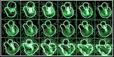 |
| In this time sequence,computed streamlines show how blood flows through the heart's mitral valve. |
There are at least two reasons why chaos is so useful. First,
the behavior of a chaotic system is a collection of many orderly behaviors,
none of which dominates under ordinary circumstances. In recent years,
investigators have shown that by perturbing a chaotic system in the right
way, they can encourage the system to follow one of its many regular behaviors.
Chaotic systems are unusually flexible because they can rapidly switch among
many different behaviors.
| SUDDEN DEATH One night in 1991, 26-year-old James Graham-Rowe
died suddenly. There was no warning. He was generally fit and healthy. The
coroner was so perplexed he ordered three post-mortems and eventually called
James's parents to apologise for his failure to find a cause for their son's
death. Twelve years later, the evidence suggests that James suffered from
a genetic disease that affects the electrical activity of the heart but leaves
the organ itself looking perfectly healthy. The first symptom of this condition
is often the last: the heart simply stops beating properly. Scientists suspect
that Brugada syndrome, as it is called, could be jeopardising clinical
trails of a host of new drugs. It may even be behind some cases of cot deaths.
[New Scientist] |
Second, although chaos is unpredictable, it is deterministic.
If two nearly identical chaotic systems of the appropriate type are impelled,
or driven, by the same signal, they will produce the same output, even though
no one can say what that output might be see "The
Amateur Scientist," page 101].This phenomenon has already made possible
a variety of interesting technologies for communications.
For more than a century, chaos has been studied almost exclusively
by a few theoreticians, and they must be credited for developing some of
the concepts on which all applications are based. Most natural systems
are nonlinear :
a change in behavior is not a simple function of a change in conditions.
Chaos is one type of nonlinear behavior.The distinguishing feature of chaotic
systems is that they exhibit a sensitivity to initial
conditions. To be more specific, if two chaotic systems that are nearly
identical are in two slightly different states, they will rapidly evolve
toward very different states.
To the casual observer, chaotic systems appear to behave in
a random fashion. Yet close examination shows that they have an underlying
order. To visualize dynamics in any system, the
Irish-born physicist
William
Hamilton and the German mathematician Karl Jacobi and their
contemporaries devised, more than 150 years ago, one of the fundamental concepts
necessary for understanding nonlinear dynamics: the notion of state space.
Any chaotic system that can be described by a mathematical equation
includes two kinds of variables: dynamic and static. Dynamic variables are
the fundamental quantities that are changing all the time. For a chaotic
mechanism, the dynamic variables might be the position of a moving part and
its velocity. Static variables, which might also be called parameters, are
set at some point but then are never changed. The static variable of a chaotic
mechanism might be the length of some part or the speed of a motor.
|
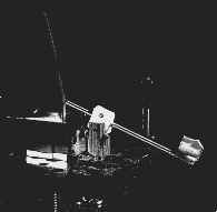
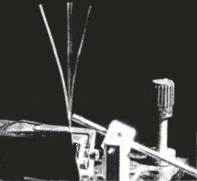
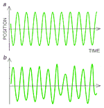
METALLIC RIBBON sways chaotically in a magnetic field whose strength fluctuates periodically. Recent advances make it possible to control such chaotic motions. The ribbon is made of a material whose stiffness depends on the strength of the field. The magnetic field changes at a rate of around one cycle per second. A strobelight flashes at the same frequency so that long-exposure photography captures the irregularities in be motion of the ribbon. A computer system analyzes the movement of the ribbon using a scheme developed by theorists at be University of Maryland. By making slight changes to the field, the computer system can transform the chaotic motions (top) to periodic oscillations of almost any frequency (bottom). |
|
State space is essentially a graph in which each axis is associated
with one dynamic variable. A point in state space represents the state of
the system at a given time. As the system changes, it moves from point to
point in state space, defining a trajectory, or curve. This trajectory represents
the history of the dynamic system.
Chaotic systems have complicated trajectories in state space.
In contrast, linear systems have simple trajectories, such as loops [see
box on page 64]. Yet the trajectory of a chaotic system is not
random ; it passes through certain regions
of state space while avoiding , others. The trajectory is drawn toward a
so-called chaotic
attractor, which in some sense is the very essence of a chaotic system.
The chaotic attractor is the manifestation of the fixed parameters and equations
that determine the values of the dynamic variables.
So if one measures the trajectory of a chaotic system, one
cannot predict where it will be on the attractor at some point in the distant
future. The chaotic attractor, on the other hand, remains the same no matter
when one measures it. Once researchers have obtained information about the
chaotic attractor of a system, they can begin to use chaos to their
advantage.
In 1989 one of us (Pecora) discovered that a chaotic system
could be built in such a way that its parts would act in perfect synchrony.
As is well known, isolated chaotic systems cannot synchronize. If one could
construct two chaotic systems that were virtually identical but separate,
they would quickly fall out of step with each other because any slight difference
between the two systems would be magnified. In some cases, however, the parts
of a system can be arranged so that they exhibit identical chaotic behavior.
In fact, these parts can be located at great distances from one another,
making it possible to use synchronized chaos for communications.
To build a chaotic system whose parts are synchronous, one
needs to understand the concept of stability. A system is stable if, when
perturbed somewhat, its trajectory through state space changes only a little
from what it might have been otherwise. The Russian
mathematician Aleksandr M.
Lyapunov realized that a single number could be used to represent the
change caused by a perturbation. He divided the size of the perturbation
at one instant in time by its size a moment before. He then performed the
same computation at various intervals and averaged the results.
This quantity, now known as the Lyapunov multiplier, describes
how much, on average, a perturbation will change. If the Lyapunov multiplier
is less than one, the perturbations die out, and the system is stable. If
the multiplier is greater than one, however, the disturbances grow, and the
system is unstable. All chaotic systems have a Lyapunov multiplier greater
than one and so are always unstable. This is the root of the unpredictability
of chaos.
The parts of a chaotic system must be stable if they are to
be synchronized. This does not mean that the entire system cannot be chaotic.
If two similar, stable parts are driven by the same chaotic signal, they
will both seem to exhibit chaotic behavior, but they will suppress rather
than magnify any differences between them, thereby creating an opportunity
for synchronized chaos.
One design developed by Pecora and Thomas L. Carroll of the
U.S. Naval Research Laboratory uses a subsystem of an ordinary chaotic system
as the synchronizing mechanism. They first distinguished the synchronizing
subsystem from other supporting parts and then duplicated the synchronizing
subsystems [see illustrations on opposite page]. The supporting subsystem
then supplied a driving signal for the original synchronizing subsystem and
its duplicate.
If the synchronizing subsystems have Lyapunov multipliers that
are less than one, that is, if these subsystems are stable, they will behave
chaotically but will be in complete synchrony. The stability of the subsystems
guarantees that any small perturbations will be damped out, and therefore
the synchronizing subsystems will react to the signals from the supporting
subsystem in practically the same way, no matter how complex the signals
are.
To demonstrate synchronized chaos initially, Pecora created
a computer simulation based on the chaotic Lorenz system, which is named
after American meteorologist
Edward N. Lorenz, who in 1963 discovered
chaotic behavior in a computer study of the
weather. The Lorenz system has three dynamic variables, and consequently
the state-space picture of such systems is three-dimensional. Plotting the
trajectory of the Lorenz system in state space reveals what is known as the
Lorenz chaotic attractor [see "Chaos," by James P. Crutchfield, J. Doyne
Farmer, Norman H. Packard and Robert S. Shaw; SCIENTIFIC AMERICAN, December
1986].
For the computer simulation. Pecora started with the three
dynamic variables of the Lorenz system and chose one of them as the driving
signal. The subsystem consisting of the two remaining dynamic variables was
then duplicated. Although the subsystem and its duplicate were initially
set up to produce different outputs, they quickly converged, generating chaotic
signals in synchrony. In state space the two subsystems began at different
points, caught up to each other and waltzed about on their chaotic attractors
in a synchronized ballet.
 |
Representing Chaos
|
Until this discovery, scientists had no reason to believe that
the stability of a subsystem could be independent of the stability of the
rest of the system. Nor had anyone thought that a nonlinear system could
be stable when driven with a chaotic signal.
Stability depends not only on the properties of the subsystem
itself but on the driving signal. A subsystem may be stable when driven by
one type of chaotic signal but not when driven by another. The trick is to
find those subsystems that react to a chaotic signal in a stable way. In
some cases, the stability of a subsystem can be estimated using a mathematical
model, but in general such predictions are difficult.
Investigators have only begun to experiment with synchronized
chaos. In 1989 Carroll built the first synchronized chaos circuit. By duplicating
part of a circuit that exhibited chaotic behavior, he created a circuit in
which the subsystem and its duplicate were driven by the same chaotic
signal.These two subsystems generated voltages that fluctuated in a truly
chaotic fashion but were always in step with each other.
Carroll realized that his synchronized chaos circuit might be
used for a private communications system. For
example, imagine that Bill wants to send a secret message to Al. Bill has
a device that generates a chaotic drive signal, and he has a subsystem that
reacts to the signal in a stable way. Al has a copy of the subsystem. Bill
translates his secret message into an electronic signal and combines it with
the chaotic output of his subsystem. Bill then transmits the encoded message
as well as the drive signal.
Anyone who intercepts these signals will detect only chaotic
noise and will be unable to extract any information (unless, of course, he
or she manages to get a copy of Bill's or Al's subsystem). When Al receives
the drive signal , he sends it through his subsystem, which reproduces the
chaotic output of Bill's subsystem. Al can then subtract this output from
the encoded information signal to recover the secret message.
It is rather easy, as Carroll has demonstrated, to recover
signals buried in chaos. To build a practical, secure communications system,
however, engineers will probably need to develop sophisticated schemes in
which the encoding process involves more than just adding chaos to message
signals.
|
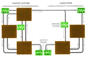
CHAOTIC SIGNALS produced by a system and a subsystem can be generated in complete synchrony. The important feature of the system is that the blue and green components are stable when driven by the chaotic signals from the red part. In other words, small changes in the initial settings of be blue and green parts have little or no effect on the behavior they eventually settle into. The subsystem consists of duplicates of the blue and green components of be system. Although the red, blue and green parts of the system send signals to one another, there is no feedback between be red component and the subsystem. |
|
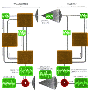
PRIVATE COMMUNICATIONS can be achieved using the scheme for synchronized chaos [see upper illustration on this page]. The transmitter adds a chaotic signal to a message signal; it then broadcasts be encoded signal and a drive signal. The drive signal is sent to two components in be receiver, causing them to generate a chaotic signal in synchrony with be signal produced in the transmitter. The chaotic signal is then subtracted from the encoded signal to yield the original information. |
Researchers at the Massachusetts Institute of Technology,
Washington State University and the University of California at Berkeley
are building new combinations of chaotic subsystems for signal processing
and communications. We have also continued our work and found a chaotic system
that performs the same operations as a phase-locked loop-a device that, among
other things, allows an FM radio receiver to track the changes in the transmitted
signal.
Carroll and Pecora had such success with using chaotic signals
to drive stable parts of chaotic systems that they suspected there might
be an advantage to employing chaotic signals to drive stable periodic systems.
Their intuition led them to another series of promising applications. Imagine
two systems that are driven by the same periodic signal and have the
same nonchaotic period-two attractor. The term "period two" means that in
two periods of the driving signal, the system travels around the attractor
once. If two such systems are driven with the same signal but are initially
at opposite ends of the attractor, they will cycle around the attractor and
never catch up to each other. In other words, if the two systems start out
of phase, they will remain out of phase forever.
By changing the periodic driving signal to a certain type of
chaotic signal, workers have recently discovered that two systems can be
coaxed to operate in phase. Yet not all types of chaotic signals will perform
this task. Some such signals may cause the system themselves to behave
chaotically, thereby eliminating any chance of getting them in phase. Engineers
must therefore figure out what type of chaotic signal to use for each kind
of system.
A good first choice is the signal produced by a system originally
invented by Otto E.Rössler. The Rössler signal is nearly periodic
and resembles a sine wave whose amplitude and wavelength have been randomized
somewhat from one cycle to the next. Such signals, which have come to be
known as pseudoperiodic, can be made, in general, simply by taking a periodic
signal and adding chaos to it. If several identical systems whose attractors
are all period two or greater are driven by the appropriate pseudoperiodic
signal, they will all get in step.
This application was first demonstrated by Carroll in 1990.
He built a set of electronic circuits that had period-two attractors and
drove them with one of several pseudoperiodic signals, including the
Rössler type. In each case, he found he was able to solve the out-of-step
problem. Yet the circuits did get out of phase for short periods. That occurred
because it is impossible to build several circuits that are exactly the same.
Nevertheless, it is quite feasible to keep the circuits in phase 90 percent
of the time.
Whereas some investigators have searched for uses of chaos,
others have sought to control it. One key to this effort lies in the realization
that a chaotic attractor is an infinite collection of unstable periodic
behaviors. The easiest way to illustrate this point is to consider a system
consisting of a weight, a "nonlinear" spring and a motor. One end of the
spring hangs from the motor; the other is attached to the weight. The motor
lifts the spring up and down with a force that can be adjusted. The dynamic
variables of the system are the position of the weight and its velocity,
and these define the state space. If the driving force of the motor is weak,
the weight will move up and down once for each cycle of the motor. At the
same time, the weight speeds up and slows down, and therefore the trajectory
in state space is a single loop, or what is technically called a period-one
orbit.
If the driving force of the motor is increased somewhat, the
period-one orbit becomes an unstable behavior, and the weight will move up
and down once for every two cycles of the motor. In state space the trajectory
is now a double loop, or period-two orbit. If the driving force is increased
again, the period-two orbit becomes unstable, and a period-four orbit will
emerge. Indeed, if the driving force is sufficiently strong, all periodic
orbits become unstable, and a chaotic attractor will appear. In a rigorous
sense, the chaotic attractor is an ensemble of unstable periodic orbits.
Four years ago Edward Ott, Celso Grebogi and James A. Yorke
of the University of Maryland developed a scheme in which a chaotic system
can be encouraged to follow one particular unstable orbit through state space.
The scheme can therefore take advantage of the vast array of possible behaviors
that make up the chaotic system.
The method devised by Ott, Grebogi and Yorke (referred to as
OGY ) is conceptually straightforward. To start, one obtains information
about the chaotic system by analyzing a slice of the chaotic attractor. After
the information about this so-called
Poincaré section has been gathered,
one allows the system to run and waits until it comes near a desired periodic
orbit in the section. Next the system is encouraged to remain on that orbit
by perturbing the appropriate parameter. One strength of this method is that
it does not require a detailed model of the chaotic system but only some
information about the Poincaré section. It is for this reason that
the method has been so successful in controlling a wide variety of chaotic
systems.
| CHAOTIC ATTRACTOR consists of many periodic orbits-for example, the period-one orbit and the period-two orbit. This attractor represents a system whose velocity and position change along a single direction. One axis represents position, and the other is velocity. Attractors may be multidimensional because systems can have many different state-space variables, that is, positions and velocities that vary in three dimensions. | 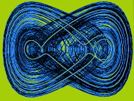 |
The practical difficulties of the OGY method involve getting
the Poincaré section and then calculating the control perturbations.
One of the simplest ways to obtain a Poincaré section is to measure,
at some regular interval, the position of the state-space trajectory of the
system. For example, the measurements could be made at the end of every cycle
of the driving signal. This technique produces a map in which a period-one
orbit appears as one point, a period-two orbit appears as two points and
so on.
To calculate the control perturbations, one analyzes the
Poincaré section to determine how the system approaches the desired
orbit, or fixed point. This analysis requires three steps. First, one determines
the directions along which the system converges toward or diverges away from
the fixed point Second, one must obtain the rate of convergence or divergence-a
quantity that is related to the Lyapunov multiplier. Last, one must figure
out how much the orbit shifts in phase space if the control parameter is
changed in one way or another. This three-step calculation provides the
information necessary to determine the perturbations that will nudge the
system toward the desired periodic orbit.
When the control parameter is actually changed, the chaotic
attractor is shifted and distorted somewhat. If all goes according to plan,
the new attractor encourages the system to continue on the desired trajectory.
If the system starts to go astray, the control parameter is changed again,
producing yet another attractor with the desired properties.
The process is similar to balancing a marble on a saddle. If
the marble is initially placed in the center of the saddle, it tends to roll
off one side or the other but is unlikely to fall off the front or back.
To keep the marble from rolling off, one needs to move the saddle quickly
from side to side. Likewise, one needs to shift the attractor to compensate
for the system's tendency to fly off the desired trajectory in one direction
or another. And just as the marble reacts to small movements of the saddle,
the trajectory is very sensitive to changes in the attractor.
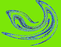 |
POINCARÉ SECTION is, more or less, a perpendicular slice through a chaotic attractor, in this case, a three-dimensional version of the attractor shown on the opposite page. The points of the Poincaré section represent different unstable periodic orbits. The period one orbit is a single point (red), and the period-two orbit is two points (blue). The determination of the Poincaré section is a key step in controlling chaos. |
What is truly extraordinary about the work of Ott, Grebogi and
Yorke is that it showed that the presence of chaos could be an advantage
in controlling dynamic behavior. Because chaotic systems are extremely sensitive
to initial conditions, they also react very rapidly to implemented controls.
In 1990 one of us (Ditto), along with Mark L. Spano and Steven N. Rauseo
of the Naval Surface Warfare Center, set out to test the ideas of Ott, Grebogi
and Yorke. We did not expect things to work right away. Few theories ever
survive initial contact with experiment. But the work of Ott, Grebogi and
Yorke proved to be an exception. Within a couple of months we achieved control
over chaos in a rather simple experimental system.
The experiment requires a metallic ribbon whose stiffness can
be changed by applying a magnetic field. The bottom end of the ribbon is
clamped to a base; the top flops over either to the left or right When the
ribbon is exposed to a field whose strength is varied periodically at a rate
around one cycle per second, the ribbon buckles chaotically. A second magnetic
field served as the control parameter.
Our goal was to change the chaotic motion of the ribbon to
a periodic one by applying the OGY method. We first needed to obtain the
Poincaré map of the system's chaotic attractor. The map was created
by recording the position of the ribbon once per drive cycle, that is, the
frequency with which the magnetic field was modulated. A computer stored
and analyzed the map; it then calculated how the control parameter should
be altered so that the system would follow a period-one orbit through state
space. We found that even in the presence of noise and imprecise measurements,
the ribbon could easily be controlled about an unstable period-one orbit
in the chaotic region. We were genuinely surprised at how easy it was to
implement and exploit the chaos.
The ribbon remained under control without a failure for three
days, after which we got bored and wanted to attempt something else. We tried
to make the system fail by adding external noise, altering the parameters
and demonstrating the system to visitors (a sure way to make any experiment
fail). In addition, we succeeded in forcing the system to follow period-one,
period-two and period-four orbits, and we could switch between the behaviors
at will.
As often happens in science, discoveries lead in unexpected
directions. Earle R. Hunt of Ohio University took notice of our experiments
and decided to attempt to control chaos in an electronic circuit. Hunt's
circuit was made out of readily available components. He was able to coax
the system into orbits with periods as high as 23 and at drive frequencies
as high as 50,000 cycles per second. Not only did he prove that chaos could
be controlled in electronic circuits, but he also showed that scientific
advances can be made on a low budget.

Hunt's chaos controller-which employs a variation of the OGY
method- has the advantage that it eliminates the need to obtain a Poincaré
section; information for the controller can be obtained directly from
measurements of the chaotic behavior. Hunt's circuit enables the manipulation
of chaos in rapidly changing systems. Armed with these results, Hunt attended,
in October 1991, the First Experimental Chaos Conference, having solved a
problem he did not know existed.
Hunt had unknowingly overcome a technological obstacle that
had stymied Rajarshi Roy and his colleagues at the Georgia Institute of
Technology. Roy had been studying the effects of a "doubling crystal" on
laser light. The crystal doubles the frequency of the incident light or,
equivalently, halves the wavelength. The laser used by Roy generated infrared
light at a wavelength of 1,064 nanometers, and the crystal converted the
light to green at a wave- length of 532 nanometers. The crystal did not work
perfectly, however. If the doubling crystal was oriented in certain ways,
the intensity of green light would fluctuate chaotically.
Roy was eager to control the chaos in the laser system, but he knew the OGY
method would not work, because it was difficult and impractical to obtain
the Poincaré section for the laser system. Furthermore, Roy was skeptical
that a computer system could perform calculations fast enough to implement
the OGY method. Fortunately, he had learned about Hunt's work at the conference.
Less than two weeks later Roy constructed a prototype controller for their
laser, and to their astonishment, it worked on the first try. Within days
they were controlling periods as high as 23 and at driving frequencies of
150,000 cycles per second.
Roy demonstrated that he could control chaotic fluctuations in the laser
intensity and could stabilize unstable high-period oscillations. The energy
of the laser could therefore be dumped into desired frequencies instead of
being distributed across a broad band of frequencies. (Roy has also employed
this technique to eliminate almost completely intensity fluctuations in his
laser system.) Consequently, investigators can design laser systems with
more flexibility and stability than ever before.
The field of laser research has also benefited from other advances
in chaos control. For example, the team of Ira B. Schwartz, Ioana A. Triandaf,
Carroll and Pecora at the Naval Research Laboratory developed a method known
as tracking to extend the range over which the control of chaos can be
maintained. Tracking compensates for parameters that change as the system
ages or that slowly drift for one reason or another.
In recent months, tracking has been applied to both chaotic
circuits and lasers with astounding results. For example, the laser remains
stable only for a very limited power range if the parameters of the control
mechanism do not adapt. By using tracking, researchers can maintain control
over a much wider power range, and amazingly, they find they can increase
the output power by a factor of 15.
One problem with the OGY method is that an unacceptable amount
of time may elapse as one waits for the system naturally to approach the
desired orbit in the chaotic attractor. Troy Shinbrot and his colleagues
at the University of Maryland and the Naval Surface Warfare Center have
demonstrated a technique that rapidly moves the chaotic system from an arbitrary
initial state to a desired orbit in the attractor. When Shinbrot and his
co-workers implemented their method in the magnetic-ribbon experiment, they
were able to reduce the time needed to acquire unstable orbits by factors
as high as 25.
Another collaboration that emerged from the First Experimental
Chaos Conference led to the first technique for controlling chaos in a biological
system. The team-which included Ditto, Spano, Alan Garfinkel and James N.
Weiss of the School of Medicine, University of California at Los Angeles-studied
an isolated part of a rabbit heart. We were able to induce fast, irregular
contractions of the heart muscle by injecting a drug called ouabain into
the coronary arteries. Once this arrhythmia started, we stimulated the heart
with electric signals that were generated according to a scheme we adapted
from the OGY method. These seemingly random signals were sufficient to establish
a regular beat and sometimes reduced the heart rate to normal levels. On
the other hand, signals that were random or periodic did not stop the arrhythmia
and often made it worse.
Investigators have already begun to test whether variations
of the OGY method could be used to control arrhythmias in human hearts. They
suspect the technique might work for atrial or ventricular fibrillation,
in which upper or lower chambers of the heart contract irregularly and cease
to pump blood effectively. In the near future, it may be possible to develop
pacemakers and defibrillators that take advantage of techniques for controlling
chaos.
Scientists and engineers have just begun to appreciate the
advantages of designing devices to exploit, rather than avoid, nonlinearity
and chaos.Whereas linear systems tend to do only one thing well, nonlinear
devices may be capable of handling several tasks. Nonlinear applications
promise more flexibility, faster response and unusual behaviors. As we continue
to investigate the nonlinearity inherent in natural and physical systems,
we may learn not just to live with chaos, not just to understand it, but
to master it.
|
