|
How it works : Alternating Current and voltage |
ALTERNATING CURRENT and voltage
 |
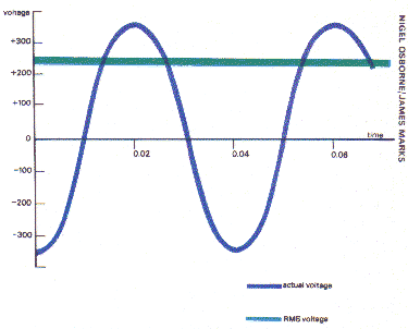
| The RMS voltage of an alternating current is a theoretical
value lower than the actual peak voltage; in the case of a 240 V RMS supply
the peak value is 339 V. |
Direct Current (DC) electricity, such as is supplied by a battery, always flows steadily in the same direction along a wire. Alternating current (AC) electricity, however, which is used for mains supplies in most countries, flows first in one direction then the other, reversing its flow at a certain frequency - usually 50 or 60 cycles a second (written 50 or 60 Hz).
For a 50 Hz frequency, the current builds up to a maximum in one direction and drops to zero in the first hundredth of a second. It builds up to a peak in the opposite direction and drops to zero again in the next hundredth of a second, making a fiftieth of a second for the entire cycle.
A light bulb or an electric heating element works equally well whichever way the current is flowing, and so do electric motors designed for AC operation. So the fact that the current oscillates is quite unimportant in practice.
The advantages of AC rather than DC power supply is that its voltage can be stepped up or down using TRANSFORMERS, which have no moving parts. AC motors and alternators (AC generators) have no commutators divided metal slip rings for picking up the current and are thus more reliable than their DC counterparts, which do have commutators. The frequency is chosen as a compromise between the conflicting requirements of transformers, power lines, lighting, rotating machinery and so. In Britain, Australia, New Zealand and South Africa it is 50 Hz (cycles per second); in the US and Canada it is 60 Hz.
The voltage of AC
Most countries, including Britain, have mains electricity supplied at
about 240 volts (the US and Canada are exceptions, with 110 V). But this
voltage cannot be measured as simply as a DC voltage.
In fact, a '240 V' AC supply rises to 339 V at the peak of its oscillation. Furthermore, since the voltage rises to a peak in opposite directions alternately (+339 V and -339 V) its average value is 0 V. This is shown in the purple line in the graph on this page, which plots the voltage of a 240 VAC supply against time - the shape of the wave is called a SINE WAVE.
 |
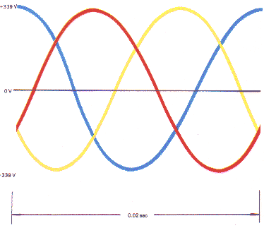
| Three phase AC, as supplied by a power station alternator, consists of three supplies along separate wires and each reaching a peak in turn within one fiftieth of a second. |
The effective average voltage produced by an alternator is that which would be produced by applying the same driving power to a DC generator of the same size. It can be found by the simple mathematical procedure of squaring the peak value since the square of a negative number is a positive number, this produces an all positive result (green line). The resulting value is then halved to give its mean (average) value (+0.5) and the square root of this is then taken (+0.707). 0.707 of 339 is 240. This value is known as the RMS (root mean square) voltage, and is the one that will be registered by an AC voltmeter connected to the mains supply.
Three phase supply
The form of AC described above is called single phase, and is the type
supplied by the ordinary domestic mains. But the alternators at a power station
supply what is known as three phase electricity. This is a way of supplying
three times as much electricity along three wires as can be supplied through
two, without having to increase the thickness of the wires. Three phase
electricity is used in industry to drive motors and other devices designed
to use it. These show the same saving in wiring for a given load.
The power station alternators have three coils equally spaced around the machine, and each of these produces a 0 Hz AC supply which is supplied to a separate wire. The way these three supplies alternate together is shown by the red, blue and yellow lines in the diagram. As the voltage in one wire reaches its peak, it is halfway to peak in the other - direction in the other two wires, so that in effect each 'burst' of electricity travels out along one wire and returns divided equally between the other two to complete the circuit.
 |
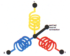
To produce three phase A C, the stator coils of an alternator are wound as shown. The neutral connection is to correct any temporary imbalance between the windings caused by unequal demand. |
The alternators are wound as shown in the diagram. If exactly the same amount of electricity were drawn from each phase wire, there would be no need for more than three electrical connections. But in practice, the three phase supply, its voltage suitably stepped down by transformers, is converted to single phase by connecting one of the phase wires to one third of the houses in a particular area.
Inevitably, the load is never quite equally balanced between the houses, which means that an imbalance of voltage builds up between the phase wires. This is overcome by earthing [grounding] the connection between the three phases at the alternator and all transformers along the line by means of a neutral wire. The surplus voltage balances itself by conduction through the ground.
Domestic single-phase AC is supplied through one phase wire and a neutral
wire running back to the transformer at the local substation. This neutral
connection is not the same as the separate earth [ground] used in electric
power sockets in Britain and many other countries (though not in the US)
this is an additional safety device.
Reproduced from HOW IT WORKS p76