 |
How it works : Alternator |
ALTERNATOR
The alternator, like the DYNAMO, changes mechanical energy into electrical energy. The form of output, however, differs for each.
|
 |
Current from the dynamo flows in the same direction all the time, but from the alternator it changes direction at a constant rate in the form of a SINE WAVE. An ALTERNATING CURRENT like this rises to a peak value, falls to zero, rises to a peak in the opposite direction and then falls to zero again. This cycle is repeated 50 or 60 times per second in a typical power station alternator that is, a frequency of 50 or 60 Hz.
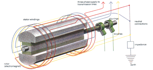
The simplest alternator is much like a simple dynamo: a loop of wire rotates between the poles of a permanent magnet, the output current being removed from the wire loop through two slip rings which rotate against 'brushes' spring loaded carbon blocks. The direction of current flow will depend on which way each half of the wire loop is cutting the magnetic lines of force. As one half descends across the face of the north pole of the magnet, the current will flow one way but will flow the opposite way when it moves upwards over the face of the magnet's south pole.
A complete cycle will be generated when the loop moves through a full 360° of rotation. Thus to generate alternating current at 50 Hz, the loop would have to turn at 50 revolutions per second or 3000 revs/minute.
Power station alternators
In power stations-and even in the small alternators found in modern cars
- the role of the rotating loop - the rotor and that of the permanent
magnet - the stator - are reversed. Thus the alternator can be imagined
essentially as a magnet in practice an ELECTROMAGNET - rotating inside coils
of wire.
There are two main reasons for arranging the machine like this. The first is that the heat generated in the rotor as a by-product of electrical power production would be difficult to remove, but the heat of a fixed stator can be removed relatively easily. The second reason is simply that the mechanical problems of conducting heavy electrical currents through slip rings and brushes are considerable.
In big machines, large amounts of heat are generated through both electrical and mechanical causes in both stator and rotor so that efficient means of cooling have to be incorporated. Typically nowadays, the fixed stator will be water cooled by pipes running parallel to the conductor wires, while the rotor will be cooled with hydrogen gas, an efficient medium which keeps unnecessary weight to a minimum.
Providing a rotor speed of 3000 revs/minute is no problem in a coal or oil fired power station, where steam turbines are used. The rotor is a two pole electromagnet turning at this speed. The simplicity of this arrangement keeps efficiency high and manufacturing costs low. The rotor itself will usually be made from solid steel with slots machined along its length to take the magnetizing coils and their hydrogen cooling ducts.
Where maintaining this speed does present a problem, as in the slower turbines of hydroelectric power stations, the number of poles is increased accordingly. For the same output frequency, four poles would allow the speed to drop to 1500 revs/minute; eight poles would reduce it to 750 revs/ minute, and so on. At such speeds the weight of the rotor becomes less critical, and the rotors of such multi-pole machines tend to be greater in diameter and shorter in length than their two-pole equivalent, thus making cooling easier. To produce the same voltage as before, the number of windings in each stator coil must be doubled or quadrupled.
 |
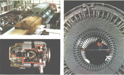
| Top left: the turbine hall of a coal fired power station.
In the smaller yellow casing is the exciter and in the larger one a 500 MW
alternator. Behind that are three turbine casings: the farthest takes high
pressure steam, the middle one intermediate pressure steam coming off the
high pressure turbine, and the nearest the low pressure steam left over.
This occupies the blue casing. Above left: a cutaway view of a car alternator. The development of cheap electronics has made it possible to convert the output to DC quite simply. Here, a diode rectifier is incorporated in the unit. Above right: lining up the segments of a generator armature. The ends of the current-producing windings are clearly visible. |
Exciting
For both types of rotor, power to magnetize them has to be generated
externally by another machine. Usually, this external exciter is on
the same shaft, rotating at the same speed as the alternator rotor. It either
generates alternating current, which is then passed through a RECTIFIER to
give the direct current required, or it generates direct current primarily.
In either case, this power will usually be fed into the alternator rotor
through brushes sliding on slip rings.This is not too much of a problem for
small alternators because of the relatively low power requirement of the
rotor- usually about 2% of the power generated in the stator. But for very
large machines, with ratings up to 1000 mega watts even 2% (20 megawatts)
would be a lot of power to feed in through slip rings.
For this reason, large machines use alternating current exciters operating with the rotor as generator and the stator as magnetic field source - the opposite way round to the main alternator - so that the power can be fed along the shaft straight into the main alternator rotor without the need for slip rings. A rectifier must also be built into the shaft.
For complete isolation from any external supply, the direct current needed for the field of the exciter is sometimes derived from a smaller permanent-magnet generator.
In power stations a typical alternator may produce electricity at several thousand volts, with a total power output of 500 to 1000 megawatts. The output is always in the form of three-phase ALTERNATING CURRENT, the stator windings being split around the machine so that there are effectively three outputs, each displaced from the next by one third of a revolution. Power in this form is cheaper to transmit than single-phase power and can be more easily utilized for driving industrial ac motors.
At the other end of the scale, alternators generating just a few hundred watts are now finding a place in cars and commercial vehicles. Because alternators use simple slip rings to feed their rotors, instead of the divided commutators used in dynamos, they can be run at a much higher speed relative to the engine, so they give high charging currents even at engine idling speeds. At the same time, because power is generated in the stator and not the rotor, they can be made smaller and lighter for the same power output.
Reproduced from HOW IT WORKS p78