 |
How it works : CIRCUIT, electrical |
CIRCUIT, electrical
An electrical circuit is designed to control the flow of ELECTRONS, that is, electric current, for a particular purpose. The purpose may be to produce heat, as with an electric cooker circuit, or light, as with an electric light circuit, or may he to remove certain frequencies from an electrical signal as with a frequency FILTER circuit.
Common components or elements used in electrical circuits include RESISTORS, INDUCTORS, CAPACITORS, POTENTIOMETERS and SWITCHES and these are interconnected by conducting wires which allow the current to flow relatively freely between the elements.
VALVES [vacuum tubes] and SEMICONDUCTORS (for example, TRANSISTORS) which
are also called electron devices-can also be connected in electrical circuits,
but such circuits are normally
called ELECTRONIC
circuits.
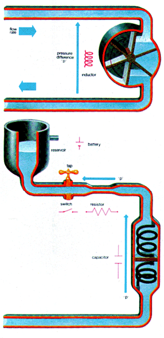
| Below: flowing water is a simple analogy to electric current; water pressure corresponds to voltage. Below a water circuit representing a battery, switch, resistor and capacitor connected in series. The constricted pipe acts as a resistor and the piston arrangement is a water storing 'capacitor'. The paddle wheel represent an inductor. |
 |
Electric current
Electric current is the flow of electrons and the unit of electric current,
the ampere (symbol A), is defined as 6.24 x10¹⁸ (6240 thousand
million million) electrons passing a given point every second.
As every electron carries a small negative electrical charge, current can also be defined as a certain amount of charge passing a given point in one second. Charge is measured in coulombs (symbol C) and one ampere is defined as one coulomb per second (1A= 1C/sec) which means that the electrical charge of an electron is 1.601x 10⁻¹⁹ coulombs.
Voltage
Electrons, as electrical charges, only move when there is a driving force
pushing them. This driving force is an ELECTROSTATIC field measured
in volts per centimetre. In this sense, electrons are similar to water.
Water will only flow when there is a pressure difference to make it flow.
This pressure difference could be the difference in height of two points
between which the rate of flow of water is being measured.
With electric current the 'pressure' difference is the voltage difference of two points between which the current is flowing.
This voltage difference (measured in volts) is sometimes called V the potential difference (pd) or the electromotive force (EMF).
Ohm's Law
Theoretically an 'ideal' conductor should exist but in reality all materials
offer some 'resistance' to the flow of electrical current-although as the
temperature falls to near absolute zero conditions improve. At all times
a potential difference is required between the ends of the conductor to make
a current flow through it. But some conductors offer more resistance than
others because a greater voltage difference is required to achieve the same
magnitude of current. A useful measure of the resistance of a conductor is
therefore the voltage difference between the ends of the conductor divided
by the current flowing through it. Georg Simon Ohm discovered that this ratio
of voltage to current was constant regardless of the size of the current.
This means that doubling the voltage across the conductor leads to twice
as much current flowing through it. Ohm's law thus states that the voltage
across a conductor divided by the current through it is a constant. This
constant is called the resistance of the conductor and is measured
in ohms. By definition one ohm is one volt per amp.
Analogies with water
Resistance means what it implies it is the 'resistance' that a conductor
presents to a flow of current. It simple analogy is water flowing through
a pipe. The resistance of the pipe to the flow of water can be measured as
the pressure difference between the ends of the pipe (equivalent to the voltage
across a conductor) which is required to make the water flow through it at
a given rate equivalent to the current flowing through a conductor) Increasing
the constriction of the pipe, such as by partially blocking it up, increases
its resistance to the flow of water and increases the amount of energy which
must be spent in pushing the water through it to maintain the same flow rate
The friction of the water against the pipe walls actually produces
a heating effect, though this is not normally noticeable. The movement of
electrons through a resistor also produces a heating effect. In an electronic
circuit this is not particularly desirable, and resistors have to be chosen
care fully according to the power they will have to handle. But the effect
is used to great advantage in an electric heater, or in a light bulb, which
glows to white heat. With electrical resistors greater resistance means greater
energy in the form of heat dissipation. Resistors are therefore used as beating
elements in electric stoves and to give light, by becoming white hot, in
ordinary light bulbs.
The water equivalent of an electrical battery is a reservoir with a constant 'head' (pressure) of water, and like a battery a water reservoir is an energy store. An electrical switch is equivalent to a simple on-off valve. Analogies of water with electricity have a certain practical limit, but to present a basic understanding of how an electrical engineer grapples with electrical circuits these analogies can be taken further. An alternating (AC) voltage supply (as with the mains supply in the home) can be considered as an alternating water pressure supply in a water circuit, with pressure applied alternately in opposite directions.
An electrical capacitor can store energy in the form of electrical charges on the surfaces of two parallel plates in such a way that the voltage between the two plates is proportional to the quantity of charge stored. An equivalent water capacitor is a cylinder with a very light piston inside held centrally by two springs one each side of the piston. A pressure difference applied across the cylinder ends forces the piston in one direction storing water (equivalent to storing charge) on one side of it at a pressure (equivalent to the voltage across the plates) determined by the tensions in the springs. The springs under tension store energy.
An electrical inductor stores energy in a magnetic field when current flows through it so that any change in the current is opposed by the changing magnetic field. It therefore permits direct (DC) currents but resists alternating (AC) currents. A simple water inductor is a water turbine. With a pressure difference applied across the openings of the turbine water starts to flow, slowly at first but faster as the turbine blades build up speed. In the process energy is being stored in the motion of the turbine blades. Eventually the blades offer no resistance to the flow of water and there is no pressure drop between the openings, Any sudden change in the water flow rate is resisted by the inertia of the rotating blades. This water inductor therefore permits a steady (or DC) flow of water but tends to resist an alternating (or AC) flow of water.
Resistance and impedance
With resistors, the relationship between voltage and current is simply
expressed by resistance, there being no energy stored in a resistor,
only energy dissipated. When, however, capacitors or inductors are
included on electrical circuits the energy stored by these elements plays
an important part in the resulting relationship between voltage and current.
Capacitors and inductors introduce a reactive component and when combined
with resistors the resistive and reactive components combine to give the
electrical circuit an impedance. The voltage-current relationships
of an impedance are different for AC and DC currents and voltages which makes
such 'complex' circuits useful for frequency filtering. For example, using
resistor- capacitor (RC) circuits or resistor-inductor (RL) circuits it is
possible to filter out the low frequency or DC components (the slow changing
components) of a signal-allowing through the high frequency (fast changing)
components required for a particular purpose.
Reproduced from HOW IT WORKS p579