 |
How it works : Logic Circuits |
Latches
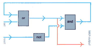
One of the commonest complex logic devices is the latch, which has
the very useful property of being able to 'remember' a signal. It has a 'set'
input which will cause the latch to turn on, and the output to become active.
It will remain active even after the set input goes inactive. To turn the
latch off (output inactive) a 'reset' line is made active. The latch is made
up of AND, OR and NOR functions which are interconnected.
 The logic
functions operate in the following manner. If both the set and reset lines
are inactive, the OR block is not 'satisfied' and the NOT function converts
its inactive output into an active output which will satisfy one input to
the AND block. The latch output is inactive. When the set line becomes active
the OR block is satisfied, and this in turn gives an active latch output
and also satisfies the other input to the AND block.
The active AND output is used to satisfy the OR block so that it will 'hold' the circuit, even when the set line goes inactive. If the reset line is now made active, the NOT function will give an inactive output which will no longer satisfy the AND block. The output from the AND block is now inactive again and consequently so are both inputs to the OR block, which results in an inactive latch output again.
This type of circuit was first described in 1919 by W H Eccles and F W Jordan, whose circuit used triode VALVES [tubes] as the NOT elements. Latches are also known as triggers, bistable multivibrator,flip-flops and toggles, and have many uses including their application in computer processor registers and stores (see also MEMORY DEVICES).
Boolean algebra
The two distinct values that are used in logic circuits represent the
choice between two alternatives. Any variable which can be expressed as one
of two alternatives is known as a logical variable or Boolean element, and
it is usual in computer technology, which is based on binary arithmetic,
to assign the symbols '0' and '1' to the two variables.

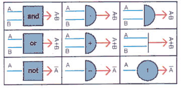
In Boolean algebra the sign for addition is '+', the sign for multiplication
is '.' and the complement (opposite) is represented by a bar over the symbol,
for example '![]() '. The complement
can also be called 'NOT', that is the complement of 'X' is 'NOT X'. It can
be seen from the tables that the addition, multiplication and complement
are identical to the respective logic functions OR, AND and NOT.
'. The complement
can also be called 'NOT', that is the complement of 'X' is 'NOT X'. It can
be seen from the tables that the addition, multiplication and complement
are identical to the respective logic functions OR, AND and NOT.
One application of Boolean algebra is in the analysis of switching circuits. The following common switching problem can be solved using Boolean algebra.
 A light,
X, for a flight of stairs, is to be controlled by two switches. One switch,
A, is upstairs, the other, B, is downstairs. It is required to be able to
switch the light on or off using either switch.
Each switch has two states designated by the symbols 0 and 1. Assuming that the light is on, then X = 1, with each switch in state 1. Changing the state of either switch must cause the light to go out. Hence X = 0 when A = 1 and B = 0, or when A = 0 and B = 1. A further change of state of a single switch must turn the light on again, hence X is also equal to 1 when A = 0 and B = 0.
A truth table for A, B and X will therefore be as follows.

The procedure for finding the expression in Boolean algebra is to take the
sum of the forms where X = 1, in this case the first and last lines of the
table which gives the result as X =
A.B+![]() .
.![]()
To put this expression into a usable form made up of the more familiar AND
and OR functions, we substitute the OR function for the addition, and the
multiplications (A.B and
![]() .
.![]() ) are replaced by AND functions. As shown in the equivalent circuit
diagram, the light will come on when the switches A AND B are both on, OR
when they are both off
(
) are replaced by AND functions. As shown in the equivalent circuit
diagram, the light will come on when the switches A AND B are both on, OR
when they are both off
(![]() AND
AND![]() ).
).
After a circuit has been represented symbolically by an algebraic expression, the rules of Boolean algebra can be used to find equivalent expressions. Each equivalent expression represents a switching circuit which could replace the original one. Thus very complicated switching arrangements can be analyzed to find the simplest circuit arrangement that will perform the desired functions.
Reproduced from HOW IT WORKS p1405