 |
How it works : Electric Motor |
ELECTRIC MOTOR
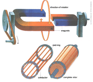 |
Left: the principle of the |
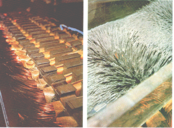
Above: a 'squirrel cage' (or nowadays, simply 'cage') induction motor has a rotor which consist of copper or aluminium bars joined at their end., by thick rings of the same material. The conductor alone is shown on the left with the complete rotor on the right. A rotating magnetic field generated in the stator induces currents in the cage which in turn produce a dragging force on the rotor and make it revolve. |
An electric motor is more properly described as an 'electric machine' for the same piece of apparatus can be used either as a motor or as a generator of electricity. There is no type of machine which can convert electrical energy into mechanical energy, which cannot convert in the opposite direction if so required.
All types of electric motor use the principles of ELECTROMAGNETISM in which either electric currents flowing in wires situated in a magnetic field experience mechanical force or in which electromagnets apply force to a ferromagnetic (intrinsically highly magnetic) material. The electric current used by motors can be either direct current (DC) as obtained from a battery, or alternating current (AC) which is generally more convenient to use, mainly because the supply voltage can be raised or lowered so effectively by static TRANSFORMERS.
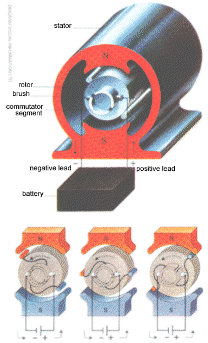
Below this perspective view of a simple DC motor shows a single coil and pair of commutator segments. The 'field' magnets are on the outside-permanent magnets are used in small motors, electromagnets in larger machines. As the rotor (armature) coil rotates, the current through the coil is periodically reversed hy the action of the commutator, thus maintaining the same direction of motive force. |
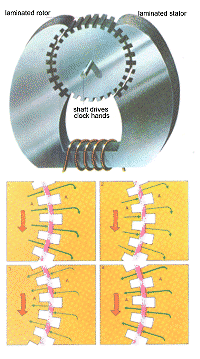
Below: a reluctance motor as used in an electric clock. The teeth on the rotor try to line up with the stator teeth. They can do this permanently by staying motionless, as shown, but since the power supply is AC, an equally acceptable condition is where the speed of rotation is such that the two sets of teeth are directly opposite each other each time the magnetic field is at a maximum. |
 |
 |
Electric motors usually produce rotational motion which is directly applicable to mechanical systems with wheels. The various types of motor can be classified into two groups:
'electromagnetic' machines and 'magnetic' machines. The electromagnetic group includes induction, synchronous, DC, AC polyphase commutator, single-phase AC commutator and repulsion motors (another form of single-phase AC commutator motor). Magnetic machines include reluctance and hysteresis motors, SOLENOIDS and RELAYS.
The classification into 'magnetic' and 'electromagnetic' machines is a comparatively recent concept and to some may seem artificial, since machines in both classes make use of electromagnets. But the difference between the two classes is of fundamental importance in appreciating the different uses to which motors of each class are put. Electromagnetic machines have a performance which improves naturally as they are made bigger. Magnetic machines, on the other hand, improve as they are scaled down to smaller sizes. The applications of reluctance and hysteresis motors arc therefore restricted to such things as tape recorders, record players and electric clocks. Electromagnetic machines, in contrast, supply the needs of both heavy and light industry alike since they are quite effective down to the size of machine needed for washing machines and even hair dryers.
One unusual form of electric motor is the LINEAR INDUCTION MOTOR. This is little more than a rotary machine which has been split along a radial plane and 'unrolled' (with minor subsequent modifications). There are as many possible types of linear motor as there are rotary types listed above.
Induction motors
When a magnet is moved across the face of an electrically conducting
sheet it induces EDDY CURRENTS in the sheet and produces a force tending
to drag the sheet along with the magnet. This fact is less well known than
the fact that a magnet will attract pieces of iron and steel, because the
conducting sheet of the induction device can (and usually does) consist of
copper or aluminium, which are classed as non-magnetic. This fact alone is
an indication that magnetic things are very effective in small sizes, while
induction devices (which are electromagnetic) are not very spectacular in
small sizes. So while the principle of the induction motor cannot be illustrated
by putting a small coin on a table and sweeping a magnet over it from side
to side, such an arrangement does produce a very small force on the coin,
and if the experiment were to be repeated with a copper disc 12 inches (30
cm) in diameter and a large magnet, a large force would be obtained.
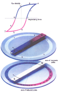
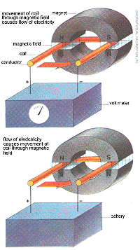
| Below: how a hysteresis motor works. The magnet, as it rotates, magnetizes the steel disc. Once magnetized, however, it is not so easily demagnetized and it tends to be dragged around with the magnet. Eventually, the disc travels at the same speed as the magnet, at which point the disc is said to be 'locked' to it. Any load on the disc will break the lock and reduce its speed. | Below: when a conductor is moved in a magnetic field a voltage is created, or induced, across it. If the ends of the conductor are connected to a voltmeter, this will give a reading when the conductor is moved. If in the place of the voltmeter a battery is connected, then a current flows through the conductor and it experiences a sideways force. This force is used to produce motion in a motor. |
 |
 |
Yet such a system cannot be described as a 'motor' because mechanical force (on the magnet) is needed to provide mechanical force on the sheet. It is, at best, a clutch. To make an induction motor, the moving magnet must be replaced by a system of fixed electromagnets which are fed with currents which change in such a way as to produce the same effect as if a permanent magnet system had moved.
For an explanation of how such a thing is possible, imagine a ring of electric lamp bulbs which are being switched on and off one at a time in sequence around the ring. If this is done fairly rapidly, the effect is as if a spot of light is travelling around the ring, yet it is obvious from the physical structure that nothing actually moves. Now suppose instead only lamp numbers 1, 4, 7, 10 and so on, are switched on for a fraction of a second, then, as they are switched off, numbers 2,5, 8, 11 are switched on, then 3, 6, 9,12 and so on, a pattern of alternate light and dark patches will appear to rotate around the ring. The rotating magnetic field of the induction motor is produced in this way by arranging a ring of magnets on the stationary part of the machine. The magnets are energized in sequence and a pattern of north and south poles appears to travel around the periphery; this field is just as capable of inducing currents in a conducting cylinder as would be a system of permanent magnets which actually moved.
Instead of 'switching' the primary ring of electromagnets, they are simply fed from an AC supply which makes the whole machine cheap to build (for it has no commutator or brushes as in a DC motor) and very robust as the rotating member consists only of what is virtually a solid lump of metal. In most commercial machines the rotating member or 'rotor 'is made up of a slotted steel core with copper or aluminium bars filling the slots and all connected together at each end of the rotor by a thick ring of the same material. In modern practice the bars and rings are usually cast into the slots at a single operation, a cooling fan often being incorporated at one end in the process of casting.
So desirable are the robust, reliable and low cost features of the induction motor, that over 90% of the world's horsepower of electric motors consists of induction machines.
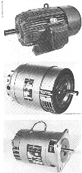
Right: a 60 hp induction motor. This is a four pole machine
operating up to 1440 rpm with a power consumption of 45 kW and a current
rating of 78.5 amps at 455 volts (three phase supply). It is built to metric
standards, being 425 mm in diameter and 926 mm long. |
 |
Synchronous motors
The production of induced current in an induction motor rotor depends
on there being relative movement between the rotating field and the
secondary conductor. In other words, the rotor never quite 'catches up' with
the field. If the rotor runs at 97% of the field speed, the 3% relative motion
is referred to as the percentage slip. It is fairly obvious that the
slip will increase with added load and for some applications such inability
to maintain an exact speed is inadmissible. In such circumstances a motor
is used whose rotor consists of an arrangement of permanent magnets or of
DC-fed electromagnets. The primary coils are, exactly as in the case of the
induction motor, arranged to produce a rotating magnetic field, but this
time the field 'locks' with the field of the magnetized rotor. Thus the rotor
speed cannot change with variation in load and it is said to run 'in synchronism'
with the mains supply.
If the system of primary coils is so arranged as to give the impression that one pair of poles, that is, a 2-pole pattern (one north pole and one south pole) are contained in the full 360°, the field will rotate one revolution in one complete cycle of the AC mains supply. In Europe the supply frequency is usually 50 cycles per second (denoted '50 hertz'). In America the standard frequency is 60 hertz. Thus a 2-pole motor On 50 Hz supply has a field speed of 50 revolutions per second or 3000 revolutions per minute (rpm). If the primary coils are arranged to give a 4-pole pattern, the speed is halved, and so on, so the possible synchronous motor speeds in Europe are 3000, 1500, 1000, 750, 600, 500 and so on, rpm. Corresponding induction motor speeds are less than these values by the small amount of slip necessary to induce secondary current. A disadvantage of the synchronous motor is that it cannot self-start and the speed must he brought to within a very small percentage of synchronism before magnetic 'locking' can take place. The synchronous machine is more commonly used as a generator or ALTERNATOR, almost all the power stations in Britain employing machines of this type.
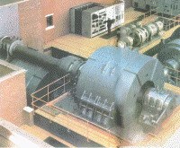
Below left: the motor room of the plantmill at the Motherwell Works of the Scottish Shelton and East Moors Group of the British Steel Corporation. This shows two 3430 kW, 1120 volts DC main mill motors with two operating speeds of 40 and 80 rpm. |
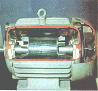
Below : a cutaway of a 3-phase squirrel cage rotor induction motor. |
 |
 |
DC and AC commutator motors
There are two disadvantages common to both induction motors and synchronous
motors. Neither is able to provide efficient speed variation over a wide
range without a variable supply frequency. Neither is able to provide speeds
over 3000 rpm when fed directly from mains supply. Where high speed or variable
speed electric drive is required for use from mains supply, a commutator
motor is used. The action of a commutator is fairly complicated and more
easily explained for the case of DC machines.
In a DC machine the stationary part (stator) consists of a ring of DC-fed 'field' magnets. The rotor is, like the induction motor, a series of conducting wires or bars in slots in a steel core. In this case, however, they are insulated coils rather than solid cast bars (and therefore more expensive to make) and each coil has its ends connected to a pair of conducting segments mounted on an insulating block on the rotor shaft at one end of the rotor. Connection to the rotor coils is made by carbon blocks or copper gauze 'brushes' which make contact with pairs of commutator segments twice per cycle. In this way current flowing in the appropriate direction can be fed to the rotor coils only when they are opposite the appropriate field pole (north or south). The 'appropriate direction' means that for all coils the force produced will he in the same direction at all speeds and loads for the ring of segments and the brushes provide automatic switching to ensure that this is so.
The disadvantage of commutator motors are that sparking tends to occur between commutator segments and brushes, which eats away the metal of the segment. Even without sparks the rubbing of brush on segments wears away both and more maintenance is required than in the case of brushless machines. Power electronics have tended to increase the popularity of the DC machine, although the small single phase AC commutator motor (generally known as a universal motor since it can also run on DC) is still the principal form of drive for household devices requiring high speed, such as vacuum 'cleaners and 'do-it-yourself power drills.
| Below left: a linear induction motor is like a rotary
motor rolled out into a straight line. This picture shows the field winding
arrangement. Below right: a study of the magnetic field pattern of a linear induction motor. A moving field will produce a force on metallic objects nearby. |
 |
Reluctance motors
A reluctance motor is simply a synchronous motor with the magnetized
rotor replaced by an unmagnetized piece of steel so shaped that it has a
number of 'preferred' positions into which it will settle for any given primary
field configuration. A preferred position is one in which the 'resistance'
of the magnetic circuit (which is called reluctance) is a minimum,
hence the name of this type of motor. The induction motor is 'king' so far
as total power of electric drives is concerned, but there are probably more
reluctance
motors in terms of numbers only, for the reluctance motor is the drive from mains-fed electric clocks, their synchronous running being frequency-dependent only. Since the main electricity supply is controlled to keep in step with Standard Time, all mains-fed clocks must indicate the same readings relative to each other. Auxiliary starting mechanisms are, of course, needed for clock motors.
Hysteresis motor
A hysteresis motor is even simpler in construction than a clock
motor for the rotor can be a smooth cylinder. The steel used to make the
rotor is, however, very similar to that used to make permanent magnets (unlike
that of all other types of motor), so that as the moving magnetic field passes
over any point on the rotor (in induction motor language we should say 'slips')
it leaves the part passed over permanently magnetized. This 'hysteretic lag'
produces force and tends to make the motor run more and more nearly as a
synchronous motor as it speeds up, until finally it succeeds in locking in
on the rotating field. Unlike the reluctance motor, however, it is capable
of driving loads at all speeds up to synchronism, but of course, synchronism
is never guaranteed, as in the reluctance machine.
Reproduced from HOW IT WORKS p851