 |
How it works : Magnetism |
MAGNETISM
Magnetism is often thought of as a force in its own right, yet it
is just one manifestation of the
electromagnetic force (see FIELDS
and FORCES). It is closely linked with electrostatic force: the difference
is that while a stationary charged particle has just an electric field associated
with it, a moving particle has a magnetic field as well. Yet it is possible
to produce permanent magnets-indeed, these are the most familiar type
-which have no apparent associated electric field. Modern physics has explained
permanent magnets in terms of electromagnetism, though as with all scientific
explanations, the theories only show the way in which things work, and fail
to clarify just why they should do so in the first place.
FARADAY, in the 1830s, demonstrated clearly the relationship between electric charge and magnetism. When electric charge moves it is said to constitute an electric current. When an electric current flows, it generates a magnetic field in the space around it just as if the current system had been replaced by a magnet system with a particular shape. It takes a force, analogous to the pressure needed to cause water to flow in a pipe, to make a charge move, that is, to produce an electric current. This force is known as an electromotive force (emf). Faraday showed that when an object capable of conducting electric current was moved through a magnetic field, an emf was set up in the conductor, capable of producing electric current. He also demonstrated that when the magnetic field which 'threaded' a conducting object was changed, an emf was also produced. So electricity produces magnetism and magnetism produces electricity.
Magnetic circuits
The concept of magnetism existing only in closed loops is a useful one
and was known to Faraday. It can be shown experimentally that the 'driving
force' in a magnetic circuit of an electromagnet (analogous to emf in an
electric circuit) is proportional both to the number of turns which form
the coil and the current in that coil. This is called the magnetomotiveforce
(mmf) and measured in ampere-turns. We then invent an imaginary
'substance' which we consider to be the result of this mmf; this we call
magnetic flux (or sometimes 'induction') and is measured in webers.
Then we can write an equivalent of OHM'S law (see
CIRCUIT, electrical) for a magnetic circuit and
use it to calculate the mmf needed to set up a certain flux or the reverse.
In electrical circuits emf equals current times resistance, and in magnetic
circuits mmf equals flux times reluctance (the impediment to the flow
of flux).
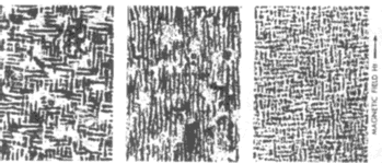 |
| Above: domain structure in Alnico 5 alloy. In A the alloy was heat treated without a magnetic field and the domains are at right angles to each other. B was heat treated with a magnetic field applied and the domains align. C is a cross section of B- the domains are 0.012 microns thick, 0.021 microns long and 0.05 microns wide. |
Permanent magnets
This tidy pattern of what is universally known as
ELECTROMAGNETISM is, however, upset by
an aspect of magnetism that has no precise counterpart in electricity. Some
elements, having been placed in a magnetic field and then removed from
it, adopt and retain an apparent internal source of mmf and they continue
to drive a flux pattern in the space around them. These we call permanent
magnets and the phenomenon 'ferromagnetism', because one of the elements
is iron (Latinferrum). The others are the less common metals cobalt and nickel
and still rarer elements such as gadolinium and dysprosium.
Many textbooks on magnetism and electricity begin with the discovery of lodestones in the Chinese desert in 3000 BC. This, and the fact that horseshoe and bar magnets have been available in toyshops for many generations, has resulted in a demand for an 'explanation' of their behaviour at a very early part of a school curriculum. The fact that the Earth itself is magnetized along an axis roughly corresponding to its axis of rotation was used by the ancient Chinese, who found that a freely suspended lodestone would always set itself in the same geographical direction. Simple rules were needed to deal with a simple action-at-distance experience, and soon the rule emerged that the lodestone had 'poles' that pointed north and south. This was followed by the rule that 'like poles repel, unlike poles attract'.
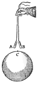
| Below left: Gilbert's experiment demonstrating induced magnetism in iron wire (A & B) by magnet (C) causing repulsive force. | |
 |
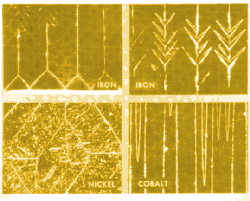
Below right: these four pictures show magnetostrictive energy in domain structure of pure iron, nickel and cobalt crystals.When magnetized, the crystals change in length and create internal strain. |
 |
|
From an educational point of view it is doubtful whether the readily available 'permanent' magnets are a blessing or a curse, for they focus attention away from the circuital nature of magnetism, which is far more useful in engineering than is the pole concept. Arguments against the circuital concept are that unlike electric circuits, magnetic circuits cannot be insulated (see INSULATOR, electric) because the corresponding magnetic conductivity of air or empty space is finite and only about a thousand times smaller than that of the best magnetically conducting steel. Faraday himself likened the design of magnetic circuits to the design of electric circuits using bare copper wire in a bath of salt water (which is a good conductor of electricity). The result is that while the electric circuits of most electrodynamic machines are complex and consist of coils of thin wire, multi-turned, their magnetic circuits are simple, short, fat and consist of a single turn.
The disadvantages of the pole concept however are first that it presupposes isolated poles in space; these have not been found, despite searches (isolated electric charges, how ever, do exist); and second, that troubles arise when trying to predict reactions between permanent magnets and other initially unmagnetized, pieces of ferromagnetic material. For this purpose the law of induced magnetism is invented, implying that the proximity of a primary magnet pole to a piece of soft iron induces an opposite pole in the latter nearest to the magnet and a similar pole at the point most remote from the magnet There are a number of experiments which are very hard to explain on the basis of poles alone, while the circuit concept sees no difficulty in such arrangements: the pieces will always take up a position of minimum reluctance (that is, minimum impediment to the flow of flux), within the prevailing mechanical constraints. The circuit theory sees a magnet's pole merely as a change in reluctance between different parts of a magnetic circuit.
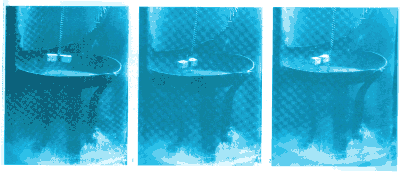 |
| Bottom: At a few degrees above absolute zero temperature the pan, which is made of lead and normally a poor conductor of electricity, becomes a superconductor (no resistance). As the magnet is lowered on the chain into the pan (1) currents are induced which set up a magnetic field to oppose the magnet. Finally, the magnet will drop no lower (2) because the induced magnetic field is large enough to support it. The chain then becomes slack (3). Superconductor electromagnets can create very large magnetic fields. |
 |
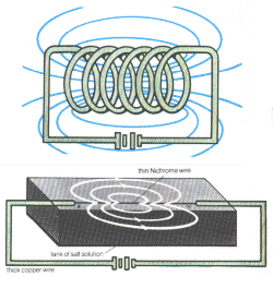 |
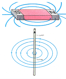
| Bottom left: current flowing in a straight
wire sets up a magnetic field pattern which may be represented as concentric
circles of 'flux'.
Top left and right: a coil of wire carrying an electric current
sets up a magnetic field the same shape as that from a bar magnet. |
|
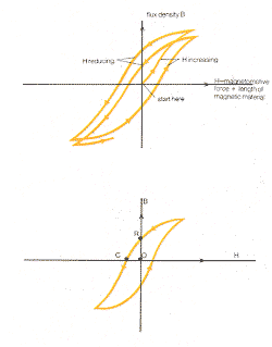 |
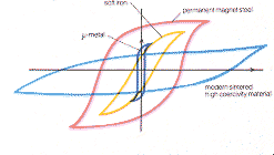
Left: a typical magnetic journey' as the result of an oscillating
magnetomotive force (mmf) in a ferromagnetic materiaL The ultimate steady
cycle after millions of cycles is shown at left. The point R is called the
'Remanence point', the distance OR being what is left of the flux density
B after the magnetizing force H has been removed. The distance OC is called
the 'Coercivity', being the value of H required to demagnetize the specimen
completely. |
 |
|
||||
|
||||
The hysteresis loop
The difficulty with permanent magnets does not end here. The magnetic
flux density B (the number of flux 'lines' crossing unit area-measured as
webers per square metre) that can be induced in a ferromagnetic material
by imposing an mmf on it is not directly proportional to that mmf. Furthermore,
if flux density is plotted as a graph against magnetizing force H, (a quantity
obtained by dividing mmf by magnetic length and measured in ampere-turns
per metre) the state of magnetization of a piece of ferromagnetic material
is seen to depend on its entire magnetic 'history'. If taken through many
circles until a repetitive pattern occurs, the loop so obtained is called
a hysteresis loop whose area can be shown to be the work done in
taking the magnetic material around one cycle and which appears as heat in
the material itself.
The ratio B/H is given the name permeability (p) but it is clear that p is not constant as B varies. It is this aspect which becomes such an easy concept in magnetic circuits involving no ferromagnetic material, for p is then constant and is the magnetic conductivity directly usable in the magnetic circuit version of Ohm's Law.
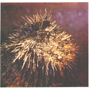 |
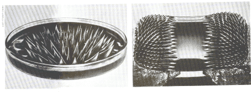
Left: permanent magnet in a sample of lodestone from
Utah, USA. At the pole, iron filings indicate lines of flux. Right: magnetic fluids (or ferrofluids) are fluids which react with magnetic fields. This shows liquid spikes forming at the surface of a magnetic fluid subject to a vertical magnetic field. Spike formation is attributed to energy balance between magnetic and interfacial tension at the surface. Far right: Despite their rigid appearance, the burrs or spikes are completely fluid and are due to the component of magnetic field that is at right angles to the free surface. |
 |
Theories of ferromagnetism
The behaviour of ferromagnetics is one of the hardest phenomena to explain
in terms of conventional physics. For several generations, Weber's theory
that all ferromagnetic substances were effectively made of a mass of tiny
particles, each of which was a permanent magnet, remained the only plausible
model, but the imagination had to be strained to account for various degrees
of difficulty being encountered in forcing the 'micromagnets' to line up,
as exhibited in the hysteresis effect.
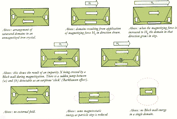
The modern (domain) theory of ferromagnetism could be said to begin with the observation of the Barkhausen effect, whereby audible 'clicks' were heard in a telephone receiver when connected to a coil of wire surrounding a ferromagnetic specimen that was being magnetized by a very gradually increasing mmf. Most of the pioneering work was done at the Bell Telephone Laboratories in the USA by a team that included Bozorth, Dillinger, Shockley (of TRANSISTOR fame) and Williams. The technique they evolved was to polish the surface of a specimen and then etch it with acid. This revealed patterns of 'walls', later to be called Bloch walls dividing regions of different magnetic orientation. The theory of these domains was then built up to the following detailed picture.
A clue to the essential difference between a ferromagnetic element and a non-ferromagnetic one is to be found in their atomic structures. The ELECTRONS orbiting the nucleus of an atom are arranged in shells, beginning with the simplest atoms 'tilling' the innermost shell and shells of large radius then being used for the electrons of elements higher in the PERIODIC TABLE, and therefore with more electrons. In order to balance the force and energies within an atom it is necessary to credit orbiting electrons with a spin (even though it is sometimes necessary to describe an electron as energy and therefore without shape).
One feature that is unique to the ferromagnetic elements is that their atoms each have at least one electron with an uncompensated spin in one of the outer shells. Latching on to this as the basis of the mechanism, it was soon shown that atoms finding themselves in relative positions such that the axes of the uncompensated spins were parallel, were likely to stay thus related and thereafter to regiment neighbouring atoms in this direction. This build up process is rapid and implies that every crystal of a ferromagnetic metal structure is self-magnetizing to saturation level.
In the case of each single crystal, however, what had hitherto been defined as the degree of magnetization was not due to each part of the crystal being magnetized to the same fraction of its saturation level. Rather the crystal is divided into portions or domains, each of which is self-saturated, but not all domains are lying in the same magnetic direction. The rules for the domains can be investigated both experimentally by the etching process and theoretically, for the crystal as a whole tries to assume a pattern of minimum total energy.
The various forms of energy in a magnetic metal crystal may be classified as follows. Firstly, there is magnetostatic energy, where the flux has to emerge from the crystal and pass through space. Secondly, there is magnetostriction energy due to the crystal increasing or decreasing in length because of magnetization, producing mechanical strain energy. Thirdly, there is Bloch wall energy due to strain in the atomic lattice where, within a distance only a few atoms thick, the spin must reverse.
When a ferromagnetic metal is reduced to finer and finer particles, the minimum energy condition is reduced to magnetization in one direction only. This knowledge gave rise to a whole new magnet technology in which fine metallic powders were shaken so as to allow them to line up with each other (just as Weber's theory stated) and the whole then heated (sintered) to make a permanent magnet with a very large coercivity. (This is the magnetizing force required to 'pull' the flux down to zero after its initial magnetization). This technique can be extended to include substances other than pure metals known as ferrites. These are CERAMIC material consisting basically of iron oxide and small quantities of TRANSITION metal oxides such as cobalt and nickel. It was found that in the ease of non metallic magnetic materials not all the electron spins within a domain were aligned in the same direction. Instead, a portion of the atoms had their uncompensated spins aligned in 6ne direction while the rest of the atoms had their spins aligned in the opposite direction. Externally, therefore, such materials cannot contain as high a flux level as can metallic substances. These ferrite substances are said to display ferrimagnetism. They are used in MICROWAVE apparatus where it is essential that the substance is nor capable of conducting electricity. Furthermore, the flux saturation level can be controlled by mixing different materials.
More recent developments have produced flexible and even liquid magnetic materials by the powder-metallurgy process. suspensions of barium ferrite and other similar materials being held in a base of rubber, polyvinyl chloride and other plastic materials. In the ease of liquids, each particle of ferrite is encapsulated in a single layer of molecules of a long-chain polymer. The capsules slide over each other with virtually no frictional resistance, so when made as a suspension in water, the liquid has the viscosity of water but the particles are so small that thermal agitation prevents them from settling.
Reproduced from HOW IT WORKS p1432