 |
How it works : Dynamo |
DYNAMO
A dynamo is a rotating machine which converts mechanical energy into electrical energy. The term 'dynamo' was originally used to cover both alternating current (AC) generators, or ALTERNATORS, and direct current (DC) generators, but nowadays it usually refers to the DC type only.
Basic principles
The dynamo, like the alternator, makes use of a phenomenon discovered
by Michael FARADAY (1791-1867). In general terms, when an electrical conductor
is moved in the vicinity of a magnet, a voltage is created, or induced,
in the conductor. If the ends of the conductor are connected in any kind
of closed electrical CIRCUIT, this induced voltage
(electrical pressure) causes a current to flow in the circuit. Mechanical
energy has been converted into electrical energy.
For a more detailed explanation it is necessary to consider the principles of ELECTROMAGNETISM. In an electrical circuit it is voltage that causes the current to flow. The voltage, or electromotive force (emf) is the cause and current the effect. By analogy, in a magnetic circuit the driving 'pressure' is called the magnetomotive force (mmf). This is the cause and magnetic flux is the result, or effect. Between the north and south poles of a magnet in the medium surrounding the magnet can be envisaged a set of flux lines- the closer these lines are together the greater the flux density. Flux density is determined by the mmf of the magnet and the permeability of the surrounding medium (see MAGNETISM).
The emf induced in an electrical conductor, moving in a magnetic field, is determined by the rate at which the conductor 'cuts' the lines of flux. The induced emf is therefore related to the speed of the conductor and the flux density. It is also related to the length of the conductor.
A simple alternator
When a closed rectangular loop of wire is mounted on a rotating axis
(the rotor) and rotated between the north and south poles of a horseshoe
magnet (the stator), the following occurs. When the two sides of the loop
parallel to the axis of the rotor (these are the 'conductors') form a line
between the north and south poles, the rate at which these two conductors
cut the lines of flux is at a maximum. The induced emf in the conductors
is therefore also at a maximum and the current flowing around the loop at
its largest value.
When the rotor has turned through 90°, the instantaneous direction of motion of the conductors is along the lines of flux. No lines of flux are therefore cut, no emf is induced in them and the loop current is zero.
When it has rotated by a further 90°, the rate of flux cutting is again a maximum with maximum emf and loop current. The loop is now, however, 'upside down' compared to its position 180° ago and the induced emf and current are a maximum in the opposite direction. A further 90° rotation and the current is again zero.
By breaking the loop at one end near the axis and connecting the ends to two slip rings on the shaft of the rotor, this alternating emf can be tapped using 'brushes' touching the rings to drive an external electrical circuit. This is the basic design of an alternator.
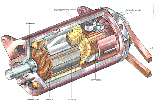
| Below: a cutaway drawing of the kind of dynamo that is used in a car. The dynamo is usually bolted to the engine and driven by the fan belt which passes over the pulley at the end. The fins on the back of the drive pulley act as a cooling fan, blowing air through the dynamo to cool the windings which would otherwise become very hot because of the current flowing through them. |
 |
From alternators to dynamos
To construct a dynamo, several loops are positioned in sequence around
the rotor. This time, instead of taking the loop ends to slip rings, they
are connected in the same sequence to individual segments of a commutator
(a divided rotating contact). Two brushes are mounted on opposite sides of
the commutator such that, as the rotor rotates, the brushes form an electrical
contact with the two ends of just one loop at a time.
By positioning the brushes so that they 'tap' that loop which is in the position of maximum flux cutting, then they will tap each loop as it comes into that position during rotation. The induced emf is therefore always in the same direction (that is, a DC voltage) and always with the maximum value possible. This is the simple dynamo.
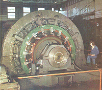
Below: this 3350 kW, 660 volt DC generator or dynamo operates at 53 rpm. The principle of the generator is that a wire moving through a magnetic field has a voltage induced in it. Here, the rotor consists of a set of wire coils mounted on a rotating shaft and connected to a commutator. The stator contains electromagnets. |
 |
Increasing the speed of rotation will, to a certain extent, increase the DC voltage available at the brushes. One other way to improve the dynamo performance is to increase the number of turns in each 'loop'-thus making a coil-because, as already stated, the length of the conductor also determines the emf that can be induced. Finally, the performance can be further improved by increasing the flux density. Several methods are available for this. First, stronger magnets or electromagnets can he employed and, second, the magnetic poles pieces can be shaped to concentrate the lines of flux.
When electromagnets are used to provide the magnetic field they draw some of the current generated by the machine. When starting from rest, the current to start the electromagnets working is derived from what little residual magnetism exists in the electromagnets and surrounding magnetic circuit.
Reproduced from HOW IT WORKS p825